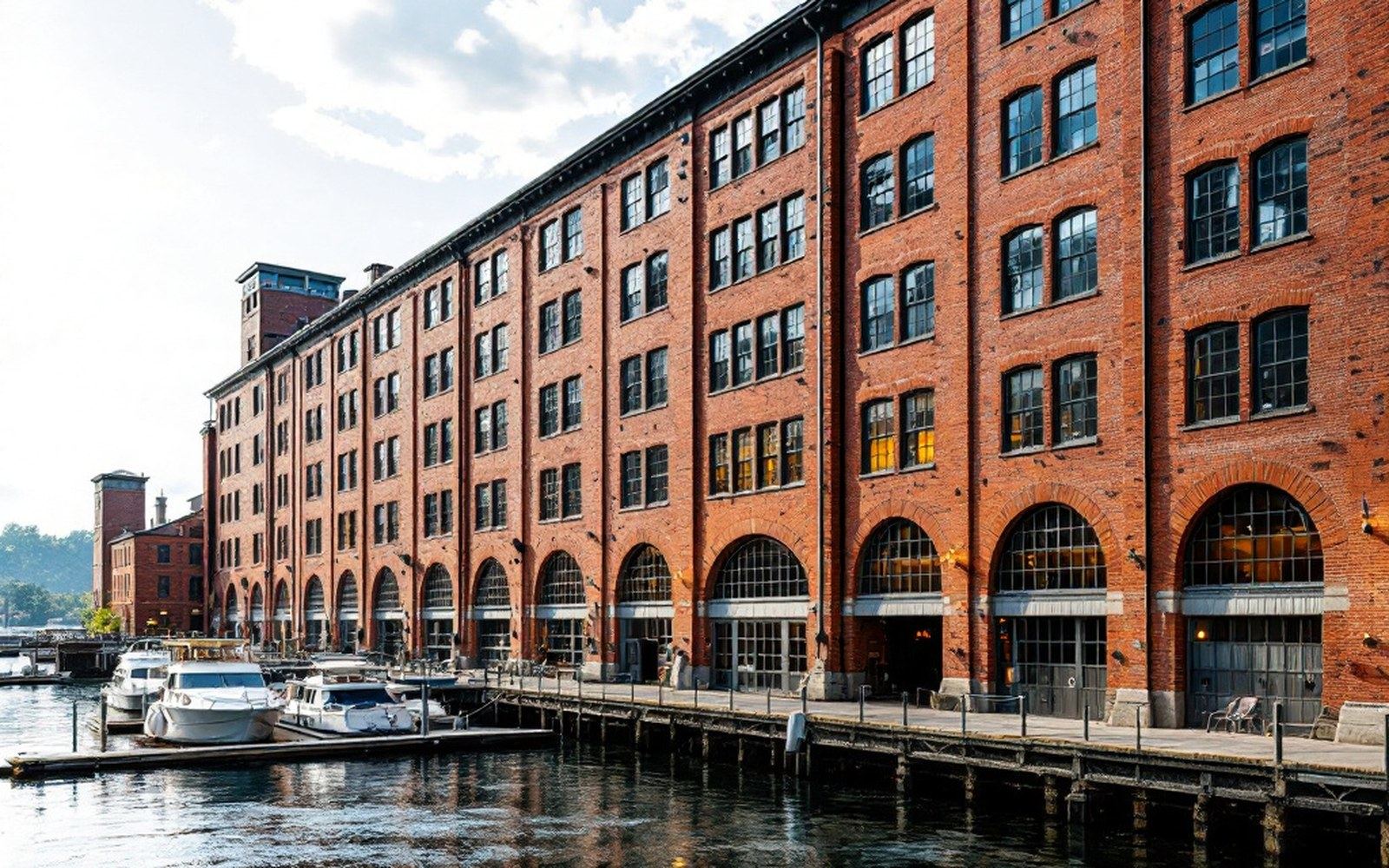
A town that sited itself on a fall
The fall, the gate and the wheel pit
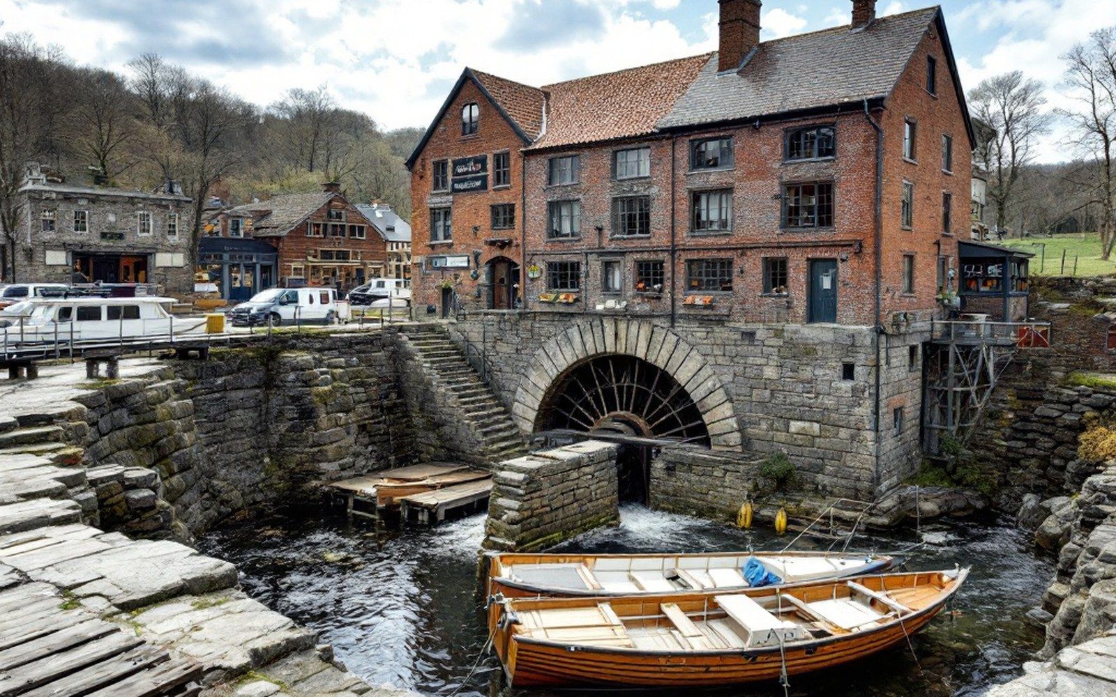
Where water became work
The drop from Lake Waukewan to Meredith Bay ↗ is modest by the standards of industrial New England — roughly ten feet of usable head under ordinary conditions — but it was consistent, and consistency was what early mill builders needed more than spectacle. The lake sat above the village like a cistern, its surface held by glacial deposits that happened to break along a single useful line, and the water that escaped that break carved the channel that the first settlers widened, lined and learned to command. The stonework they left behind is the most durable record of that command: cut granite and fitted fieldstone, sluice gate seats worn smooth by decades of iron and wood, and the rectangular void of the wheel pit that survives partly intact below grade.
To read those stones correctly, it helps to understand the three moments where the drop was controlled. The first was the intake, where water was drawn from the outflow of Waukewan into a headrace — a lined channel leading to the mill. The second was the sluice gate, the adjustable barrier that regulated how much water entered and how fast. The third was the wheel pit, the chamber excavated to receive the wheel itself, where the kinetic force of falling water was converted into rotation. Each moment left a different mark in the masonry, and each mark is still legible.
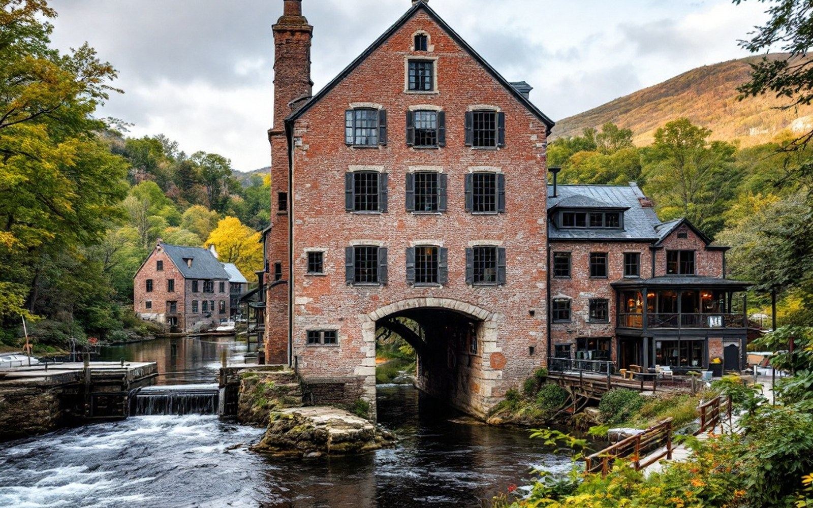
The sluice gate and what it controlled
A sluice gate is, mechanically, a door in a dam or channel wall: raise it, water flows; lower it, it stops. But the engineering of a reliable sluice gate in the early nineteenth century was more demanding than that description suggests. The gate had to slide vertically in grooves cut into the masonry with enough precision that water pressure alone would not force it sideways. It had to be heavy enough to seat under its own weight, yet light enough that a single operator could raise it by hand or with a simple screw mechanism. And the masonry surrounding it had to be waterproofed — typically with hydraulic lime mortar, which sets in the presence of water rather than drying in air — while resisting the constant saturation that would destroy ordinary mortar within a few seasons.
At Meredith, the gate seats cut into the granite threshold are still visible at the point where the headrace narrows before entering the wheel pit. They are channels approximately three inches wide and four inches deep, their sides polished by the iron shoes of successive gates over perhaps sixty years of active milling. The polish is the important detail: ordinary weathering produces roughness; sustained sliding contact under load produces this gloss. The gates that ran in these channels were replaced more than once — iron eventually replaced wood in the mid-nineteenth century, when foundry work became available through regional supply chains — but the cut stone seats, being harder than any gate material, outlasted them all. The stonework of the mill block above grade uses the same granite quarried from the same local ledge; below grade, the fit is tighter and the courses more carefully leveled, because the water demanded it.
Chronology of construction phases
- Early settlement eradry-laid fieldstone wheel pit walls, wooden sluice gates, basic headrace excavation
- Mid-nineteenth centurylime-mortar coursework, iron gate replacements, pit wall extension, mill complex enlargement
- Later nineteenth centurybranch railroad arrives; manufacturing declines; structural clearance slows
- Presentwheel pit enclosed below grade; gate seats accessible; headrace survives as drainage channel
What the operator controlled through the gate was not simply volume but timing. Mills did not run continuously. A millwright would open the gate to build up the head behind it, then regulate flow to match the pace of the machinery, then close the gate entirely when a shift ended or when the machinery required adjustment. This rhythm — fill, flow, close, fill again — shaped the working day as reliably as any clock, and the wear pattern on the gate seats reflects it: deepest at the lowest position, where the gate sat during closure, and at the upper travel limit, where it rested fully open.
The wheel pit
The wheel pit is the most architecturally significant element of the surviving hydraulic infrastructure. It is a rectangular chamber, excavated into the glacial till and lined on three sides with granite coursework and on the fourth — the downstream wall — with a combination of stone and later brick repair. Its dimensions reflect the diameter of the wheel it once contained: the pit needs to be slightly deeper than the wheel diameter to give clearance at the bottom, wide enough to allow the wheel to turn without the buckets striking the walls, and long enough along the axle line to support the bearing housings on both ends.
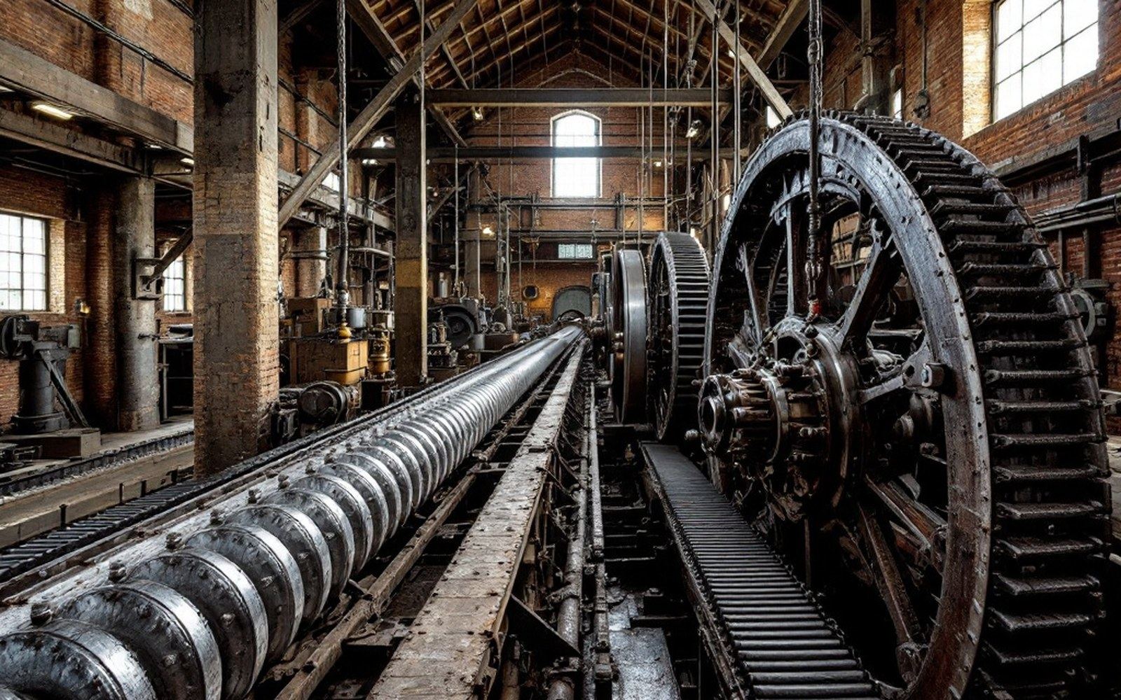
The Meredith pit's depth corresponds to a wheel of modest diameter, consistent with the overshot configuration that the available head made possible. An overshot wheel receives water at the top, relying on the weight of water in the buckets rather than its velocity to generate torque; it is the most efficient conversion of a modest but controlled head of water, and the geometry of the Waukewan outfall made it the rational choice. A breast wheel, which receives water at mid-height, or an undershot wheel, which relies on current alone, would both have wasted a significant portion of the available energy.
The downstream wall of the pit shows two distinct construction phases. The lower portion is dry-laid fieldstone, consistent with the earliest settlement-era construction; the upper courses are set in lime mortar and use more regularly cut stone, suggesting a repair or extension sometime in the middle decades of the nineteenth century, when the mill complex was enlarged. This phasing is legible in the stratigraphy of the pit walls without excavation: the change in construction technique is visible from inside the pit, where groundwater has periodically exposed the full face of the masonry. The tailrace — the channel that carried spent water away from the wheel and back toward the bay — exits through an opening in the downstream wall at a level roughly eighteen inches above the pit floor, calibrated to ensure the spent water drained clear without backing up against the wheel and robbing it of its fall.
Hydraulic mechanics: key terms
| Head of water | the vertical drop driving the wheel; roughly ten feet at Meredith under ordinary conditions |
|---|---|
| Sluice gate | adjustable barrier regulating flow into the headrace; gate seats survive as polished grooves in granite |
| Wheel pit | excavated chamber housing the waterwheel; depth calibrated to wheel diameter |
| Overshot wheel | receives water at top; weight-driven; most efficient for modest, controlled head |
| Headrace | lined channel carrying water from intake to wheel pit |
| Tailrace | channel carrying spent water from wheel pit back to the bay |
What the stones record
The survival of this infrastructure is partly practical and partly accidental. Practical because the stonework, once set, required no maintenance to persist — unlike the wooden elements of the superstructure, the iron fittings, or the machinery itself, all of which deteriorated or were salvaged. Accidental because Meredith's transition from manufacturing to resort and retail, driven by the branch railroad in the second half of the nineteenth century, left the mill complex commercially marginal at the moment when industrial clearance would otherwise have been most likely. Buildings that ceased to pay were not always demolished immediately; sometimes they simply stood until preservation became deliberate.
The wheel pit today is covered rather than exposed: subsequent construction over and around the original mill footprint has enclosed it within a basement-level space. The gate seats are accessible but not interpreted. The headrace survives in part as the channel that still carries drainage through the center of the commercial block, though what it runs through has changed entirely from what it once ran for. Taken together, these elements form a kind of stratigraphic argument: the town's founding logic — water falling from a held lake, regulated through a gate, turned in a pit — is still physically present below the streets that replaced it.